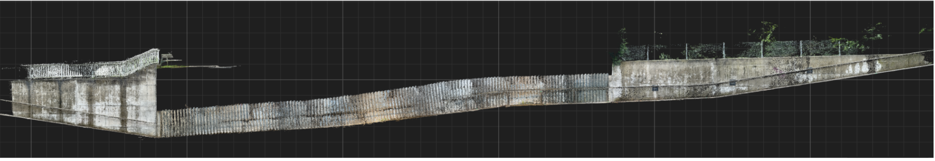
Scanning patterns accuracy results of tunnel mapping
The workflow uses off-the-shelf tools—specifically PIX4Dcatch with RTK (these tools utilize a combination of AutoTags, PIX4Dcatch’s Geofusion sensor fusion algorithm, GNSS RTK signals in open-space sections, and SFM processing).
With the mobile mapping system in place, from Part 1 of this two-part series, we tested how different scanning patterns performed in a real tunnel—and how well they held up in terms of accuracy and repeatability.
Scanning Patterns
Several scanning patterns were tested to evaluate how well they captured the tunnel environment. Each was assessed for overall model completeness, image quality, and the ability to minimize artifacts during reconstruction. The pattern that produced the most complete model was then repeated four times on different days, with AutoTags placed in new locations, to test the repeatability of the method.
Scanning patterns evaluated:
- Single direction with straight pattern: In this method, the camera moves forward in one direction while always facing straight ahead. It captures the fewest images and minimizes the chance of double-layer artifacts during reconstruction, thanks to its linear path and minimal overlap. However, it offers little to no redundancy.
- Single direction with spiral pattern: In this method, the camera is tilted and rotated in a spiral motion while moving forward in one direction. This helps capture all sides of the tunnel and improves coverage. However, it may increase the number of images and processing time compared to a straight pattern. It’s also more sensitive to rotation—if the motion isn’t smooth or is too fast, it can cause image blur.
- Double direction with straight pattern: The camera moves back and forth through the tunnel, tilted to one side, with an overlapping region created in the center between the two passes. This pattern increases redundancy and provides better coverage, especially for areas that might be missed in a single pass.
- Double direction with spiral pattern: The camera follows a spiral scanning motion while moving back and forth through the tunnel. This pattern provides the most comprehensive coverage but requires the highest number of images, potentially increasing the chances of oversampling and prolonging processing time.
Data Processing
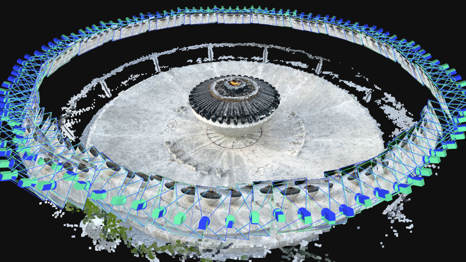
The data was processed using PIX4Dmatic, which offers advanced features like adding ground control points (GCPs), check points, and manual tie points (MTPs). The software allows users to customize the processing workflow to fit specific project needs, and all results can be visualized and further analyzed.
For example, Fig. 4 shows a section cut of the point cloud generated by the software. Checkpoints were manually marked in the images, and PIX4Dmatic automatically assessed their accuracy. These points were used only for evaluation—they did not influence the reconstruction process, and their image data was not included in the Structure from Motion (SfM) calculation.
This mapping technique relies on the precision of the image geotags to determine accuracy. Some checkpoints, especially those outside the tunnel that are easy to measure with the GNSS rover, can be used as ground control points (GCPs) along with AutoTags during the SfM process. This improves accuracy and reliability, reduces distortions, and ensures a precise final model, without requiring any additional hardware.
GeoFusion
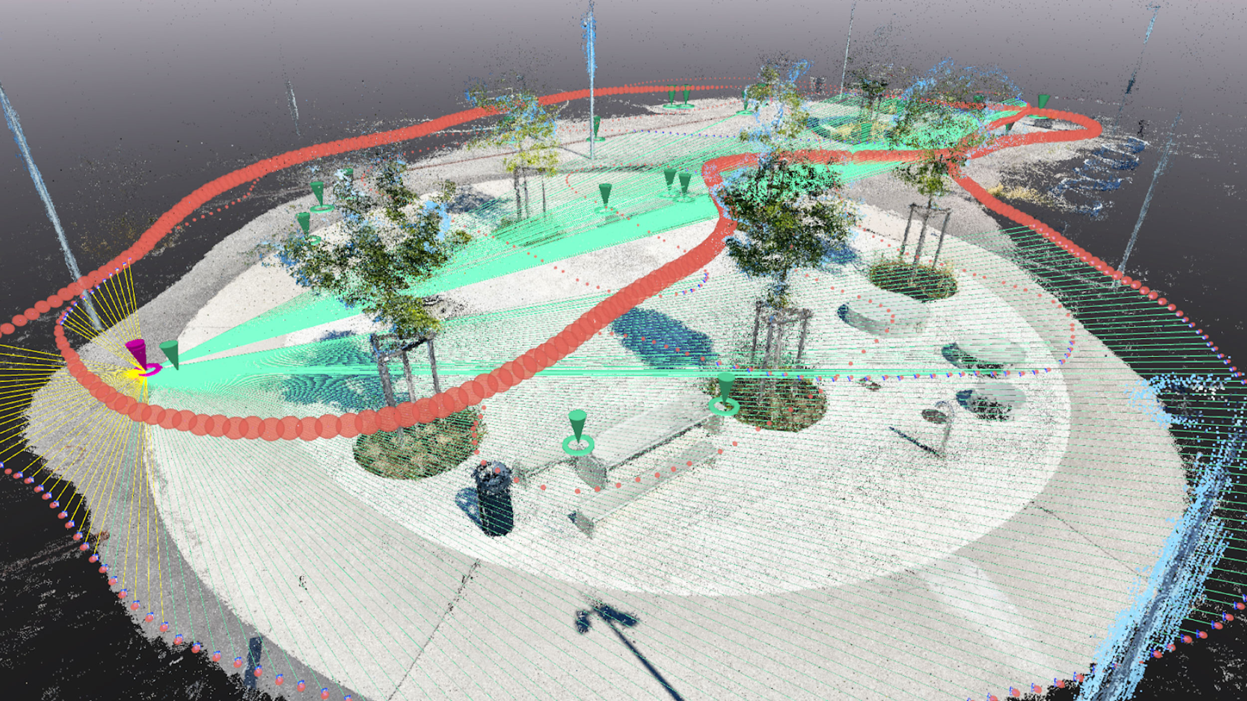
PIX4Dcatch combines data from the GNSS RTK rover and the phone’s built-in sensors to improve positioning accuracy. Each image is tagged with the estimated camera position, orientation, together with the related uncertainty, calculated after capture using Pix4D’s proprietary sensor fusion algorithm, Geofusion. PIX4Dcatch collects three types of data streams during capture:
- Position fixes from the external GNSS receiver.
- Real-time camera position and orientation from the phone’s augmented reality system (ARKit on Apple devices).
- Image coordinates of AutoTag corners, detected in real time by Pix4D’s proprietary detector.
Pix4D’s Geofusion algorithm combines data from multiple sources—including GNSS, ARKit, and Pix4D AutoTags—to estimate the precise position and orientation of each image. While GNSS provides global accuracy and ARKit offers real-time tracking, each has limitations, especially in complex environments like tunnels. GeoFusion intelligently merges these inputs, correcting for drift and errors, and fills in gaps using AutoTags placed along the scan path. The result is accurate image geotags, even in areas with poor signal or limited visual features. To learn more you can read the full paper here.
In Figure 5, you can see the position error of the camera geotags for one of the acquisitions considered in the repeatability evaluation. You can see that GeoFusion corrects the substantial drift visible in the original ARKit solution (displayed in green). Thanks to the fusion of the additional information coming from the GNSS position fixes (outside the tunnel) and AutoTags, we achieved a dm-level position error on the entire dataset. The uncertainty of the GeoFusion position estimate is also displayed in shaded red (one σ bounds). The uncertainty is higher within the tunnel, as expected, and the actual error is approximately consistent with the estimated uncertainty.
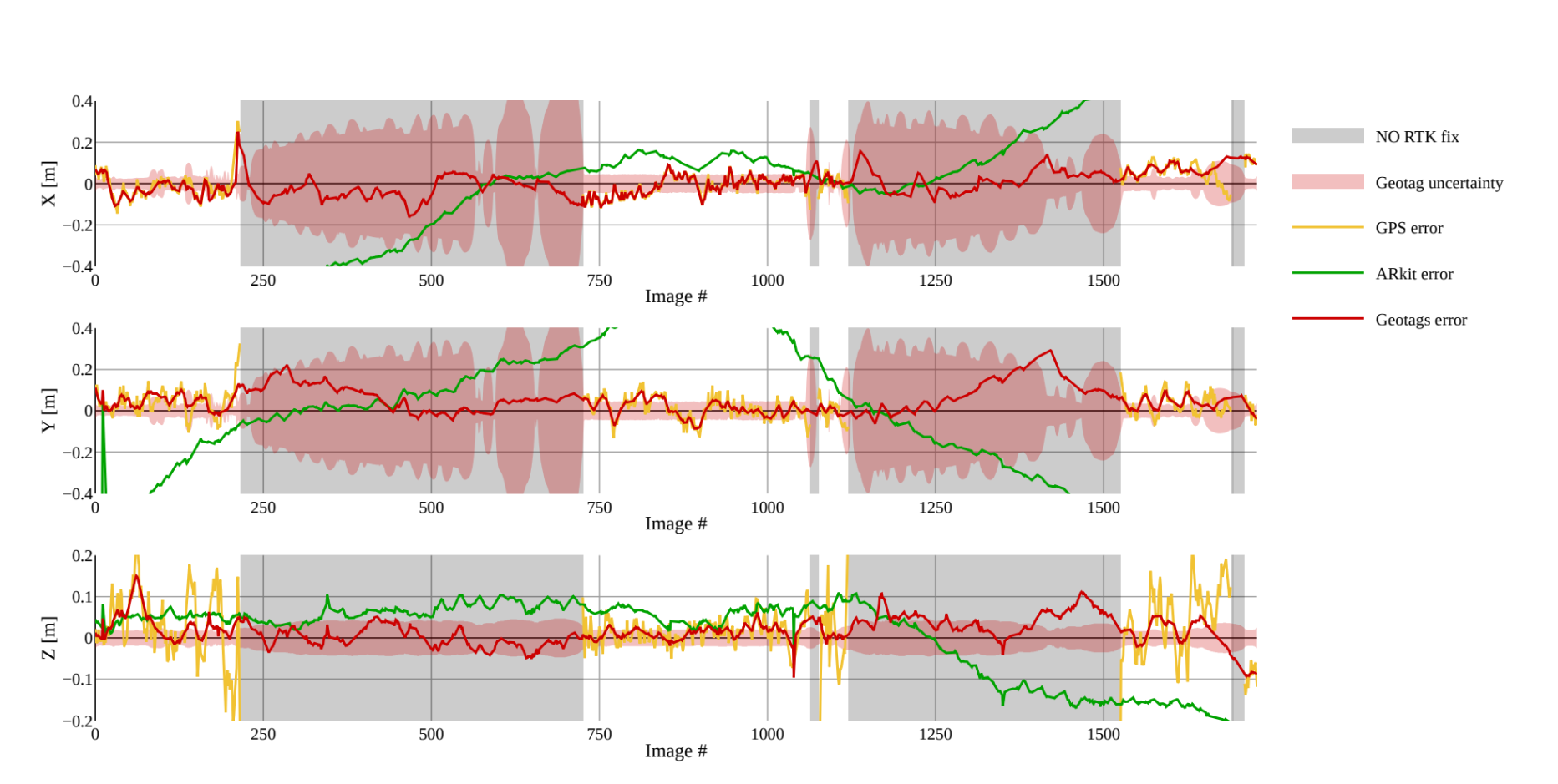
The ground truth trajectory was obtained in PIX4Dmatic by processing the data using all available checkpoints as GCPs. The geotags estimated by GeoFusion after the capture provide the prior information on camera positions and orientation that is used in postprocessing by the SFM algorithms in PIX4Dmatic.
Evaluating the scanning patterns
We evaluated the most suitable scanning patterns in terms of point cloud completeness and presence of artifacts. Four different scanning patterns were tested under the same conditions and with the same AutoTag setup. The completeness of the point clouds was evaluated in PIX4Dmatic by comparing specific areas of the tunnel across scans. Results showed that scanning in two directions (back and forth) produced more complete models than single-direction scans, which can miss areas hidden from one viewpoint. Figure 6 shows these differences.
While the oblique and spiral patterns performed similarly, each had strengths: the oblique method captured the tunnel floor more effectively, while the spiral method was slightly better at reducing occlusions.
The single-direction method with a slightly tilted forward-facing camera worked well for mapping the floor, such as for surface inspections. However, capturing the tunnel’s sides required additional images. This shows why the scanning method should match the project goal. For visual inspection, where a 2D image provides most of the content and the point cloud is used mainly for navigation, simple scanning may suffice. But if an accurate 3D model is needed for purposes such as BIM, a more thorough scanning strategy is required to generate a complete and precise point cloud or mesh.

Repeatability assessment
The double-direction spiral pattern gave the most complete results, creating a clean point cloud with no visible artifacts. To test how reliable it was, the tunnel was scanned four more times on different days, each with a new AutoTag layout. All scans were processed in PIX4Dmatic, and the accuracy of the 3D models was measured using 29 checkpoints. No ground control points (GCPs) were used during processing. As shown in Table 1, the overall accuracy, measured as the Root Mean Square (RMS) error per axis, was within a few centimeters.
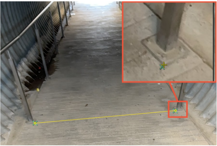
To check the relative accuracy of the 3D reconstruction, the team measured the distance between handrail supports at six points along the tunnel using a tape measure. These same points were then identified in the images using PIX4Dmatic (see Figure 8), and the distances estimated by the software were compared with the manual measurements.
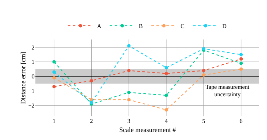
As shown above, the absolute error was always under 2.3 cm, with a mean error of less than 1 mm and a standard deviation of 1.3 cm across all tests. Since the actual distances were around 2 meters, this means the relative accuracy was better than 1%—a strong result for infrastructure monitoring tasks.
Accurate underground mapping with PIX4Dcatch’s GeoFusion
The strong results in this study were made possible by the accurate geotags calculated by PIX4Dcatch’s Geofusion algorithm, combined with Structure from Motion (SfM) processing in PIX4Dmatic. To test how important Geofusion is, an experiment was run where its geotags were replaced with raw RTK position data, and no other positioning input was used. This method is still realistic for experienced users.
This study shows that mobile phones, when combined with AutoTags, the Geofusion algorithm, and a GNSS RTK adapter, offer an accurate and affordable way to map underground environments. The method was tested in a real tunnel and delivered centimeter-level accuracy, even in areas with poor lighting, visual obstructions, and no GNSS signal.
Among the scanning patterns tested, the double-direction spiral method produced the most complete and artifact-free point clouds. While single-direction scanning works well for simple tasks like tarmac inspections, more complex tunnels benefit from two-direction scans for full coverage. AutoTags were key to maintaining accuracy, especially when merging images from different passes.
This workflow is accessible to users with little or no photogrammetry or surveying experience, and it reduces the cost and complexity compared to traditional tools like LiDAR or SLAM-based systems. Its ease of use makes it practical for a wide range of tunnel mapping tasks and supports broader adoption in construction, infrastructure, and urban planning projects.